 Tel.:
 Sales@alphageo-info.com


How Surveying Firms Can Compare LiDAR 3D Scanners for Topographic Mapping Projects
- Key Performance Criteria Every Surveying Firm Should Evaluate in a LiDAR 3D Scanner
- Environmental and Operational Factors That Determine Real-World Suitability
- Data Processing, Software Ecosystem, and Workflow Integration
- Comparing LiDAR 3D Scanner Specifications: A Practical Reference Table
- Building a Complete Topographic Survey System Around Your LiDAR Scanner
- Frequently Asked Questions
Choosing the right LiDAR 3D scanner for a topographic mapping project is one of the most consequential procurement decisions a surveying firm can make. After more than fifteen years working across land surveying, hydrographic surveying, and geophysical survey campaigns, I have watched teams lose weeks of fieldwork and tens of thousands of dollars because they selected a scanner based on brochure specifications rather than mission-critical performance criteria. In this article I walk you through the exact framework I use when comparing LiDAR 3D scanners, covering range accuracy, point cloud density, environmental resilience, workflow integration, and total cost of ownership — so your firm can move from specification sheets to confident field deployment.
Key Performance Criteria Every Surveying Firm Should Evaluate in a LiDAR 3D Scanner
Range, Accuracy, and Point Cloud Density
The first numbers I look at are maximum range and range accuracy. For open topographic mapping across large corridors — think highway alignments, river floodplains, or mineral exploration grids — you need a scanner capable of reliably capturing returns at 300 m or beyond at high reflectivity targets, with range accuracy better than ±15 mm at one standard deviation. Scanners built on time-of-flight LiDAR principles generally outperform phase-based systems at long range, while phase-based units deliver superior point density at short range for urban corridor mapping. Point cloud density, expressed in points per square meter at a given flight altitude or scan distance, directly determines your ability to extract breaklines, model drainage features, and meet deliverable specifications such as ASPRS Positional Accuracy Standards. I always request raw point cloud samples from the vendor and run them through my processing pipeline before committing to a purchase.
Scan Rate, Field of View, and Angular Resolution
Scan rate — measured in points per second — determines how efficiently you cover ground. A mobile terrestrial LiDAR 3D scanner operating at 500,000 points per second will complete a highway corridor survey in a fraction of the time required by a 100,000 points-per-second unit. However, raw speed is meaningless without adequate angular resolution. I look for horizontal and vertical angular step sizes of 0.001° or finer for precision topographic work. Field of view matters enormously in forested or canyon terrain: a 360° horizontal and 300° vertical FOV minimises occlusion shadows and reduces the number of scan positions needed. According to guidance published by the American Society for Photogrammetry and Remote Sensing, point spacing and density requirements vary by project accuracy class, and your scanner specifications must be matched to those classes before mobilisation.
IMU Quality and GNSS Integration
In mobile LiDAR scanning — whether mounted on a UAV, vehicle, or vessel — the inertial measurement unit and GNSS integration are as important as the laser itself. A weak IMU introduces trajectory errors that no post-processing algorithm can fully correct. I specifically evaluate IMU drift rates, gyroscope bias instability (ideally below 1°/hour), and the tightness of the GNSS-IMU coupling. Tightly coupled systems that share raw GNSS observables with the IMU filter maintain centimetre-level positioning even through short GNSS outages under tree canopy or near structures. This is where pairing your scanner with a high-performance GNSS receiver becomes non-negotiable — and I will return to this point when discussing integrated survey system solutions later in this article.
Environmental and Operational Factors That Determine Real-World Suitability
IP Rating, Operating Temperature, and Vibration Tolerance
Topographic mapping projects rarely happen in controlled laboratory conditions. I have deployed scanners in monsoon-season river surveys, desert mineral exploration campaigns at 45 °C, and Arctic permafrost mapping at −30 °C. An IP rating of IP54 or better is my minimum threshold for any scanner that will leave the office. For hydrographic surveying and coastal mapping, I insist on IP65 or higher. Vibration tolerance is equally critical for vehicle-mounted or UAV-mounted configurations: check the manufacturer's MIL-STD-810 or equivalent vibration test data, not just the operating temperature range printed on the datasheet. Scanners that pass rigorous environmental qualification consistently outperform those that do not when conditions deteriorate mid-campaign.
Weight, Form Factor, and Multi-Platform Compatibility
Modern topographic mapping workflows demand flexibility. The same LiDAR 3D scanner core should be deployable on a backpack frame for pedestrian surveys, a UAV for aerial acquisition, a vehicle for mobile mapping, and a survey vessel for combined land-water boundary surveys. I evaluate whether the manufacturer offers certified mounting kits for multiple platforms and whether the scanner's weight and power draw are compatible with the UAV payload limits or vehicle power systems I already operate. Lightweight scanners in the 500 g to 1.5 kg range have opened up UAV-based topographic LiDAR to projects that previously required manned aircraft, dramatically reducing mobilisation costs.
Eye Safety Classification and Regulatory Compliance
All commercial LiDAR scanners sold for surveying applications should be Class 1 eye-safe under IEC 60825-1 laser safety standards. Never assume compliance — request the certificate. In jurisdictions with strict UAV and airspace regulations, the scanner's radio frequency emissions must also comply with local telecommunications authority requirements. I always verify compliance documentation before international project deployments to avoid customs delays or operational restrictions.
Data Processing, Software Ecosystem, and Workflow Integration
Native Software Capabilities and Third-Party Compatibility
A LiDAR 3D scanner is only as productive as the software ecosystem surrounding it. I evaluate whether the manufacturer's native software handles trajectory processing, point cloud georeferencing, noise filtering, ground classification, and DTM/DSM generation in a single workflow, or whether you need to stitch together multiple third-party tools. Compatibility with industry-standard platforms — Terrasolid, LAStools, ESRI ArcGIS Pro, Autodesk Civil 3D, and open-source tools like PDAL (Point Data Abstraction Library) — is essential for firms that deliver to diverse client specifications. Proprietary data formats that lock you into a single software vendor are a long-term liability I advise clients to avoid.
Data Controller and Field QC Capabilities
Field quality control is where projects are won or lost. A capable data controller that displays real-time point cloud coverage, trajectory quality indicators, and scan overlap statistics allows the field crew to identify gaps and re-acquire data before demobilising — saving the cost of a return visit. I look for data controllers with ruggedised displays readable in direct sunlight, intuitive touch interfaces operable with gloved hands, and sufficient onboard storage and processing power to handle high-density point clouds in the field. Wireless data offload via Wi-Fi or cellular to cloud processing platforms accelerates turnaround from days to hours on large corridor projects.
Calibration Workflow and Boresight Accuracy
Boresight calibration — the precise determination of the angular offset between the LiDAR sensor and the IMU — is a critical and often underestimated step. Errors of even 0.01° in boresight angles translate to decimetric point cloud errors at 100 m range. I evaluate how the manufacturer's calibration workflow is implemented: is it automated or manual, how long does it take, and how stable are the calibration parameters over time and across temperature cycles? Scanners with stable, repeatable boresight parameters reduce recalibration overhead and increase confidence in multi-campaign data consistency.
Comparing LiDAR 3D Scanner Specifications: A Practical Reference Table
The table below summarises the key specification categories I use when comparing LiDAR 3D scanners for topographic mapping projects, along with the performance benchmarks I consider minimum, standard, and High Quality for professional surveying applications.
| Specification Category | Minimum Acceptable | Standard Professional | High Quality / High-Accuracy |
|---|---|---|---|
| Maximum Range (80% reflectivity) | 100 m | 200 – 300 m | 400 m+ |
| Range Accuracy (1σ) | ±30 mm | ±10 – 15 mm | ±5 mm or better |
| Scan Rate (points/second) | 100,000 | 300,000 – 500,000 | 1,000,000+ |
| IMU Gyroscope Bias Instability | < 10°/hour | < 2°/hour | < 0.5°/hour |
| IP Protection Rating | IP54 | IP65 | IP67 or higher |
| Operating Temperature Range | 0 °C to +40 °C | −20 °C to +50 °C | −40 °C to +60 °C |
| GNSS Integration | Loosely coupled | Tightly coupled, dual-frequency | Tightly coupled, multi-constellation RTK/PPK |
| Multi-Platform Support | Tripod only | Tripod + vehicle or UAV | Tripod + vehicle + UAV + vessel |
| Data Controller Compatibility | Laptop only | Ruggedised tablet | Dedicated ruggedised controller with real-time QC |
| Laser Safety Class | Class 1 (IEC 60825-1) | Class 1 (IEC 60825-1) | Class 1 (IEC 60825-1) |
Building a Complete Topographic Survey System Around Your LiDAR Scanner
Why the Scanner Alone Is Never the Complete Answer
After evaluating hundreds of scanner configurations across land, marine, and airborne campaigns, I am convinced that the single most common mistake surveying firms make is optimising for the scanner specification in isolation. A High Quality LiDAR 3D scanner paired with a mediocre GNSS receiver will consistently underperform a mid-range scanner paired with a high-grade multi-constellation GNSS receiver. The GNSS receiver determines the absolute positional accuracy of every point in your cloud. For topographic mapping projects requiring vertical accuracy better than 5 cm, you need a GNSS receiver capable of real-time kinematic or post-processed kinematic positioning with full multi-constellation support — GPS, GLONASS, Galileo, BeiDou — and a low-latency, high-reliability data link to a reference network or base station.
Integrating Radios, Data Controllers, and Monitoring Systems
In my experience, the field communication architecture is where integrated survey systems either excel or collapse. High-quality survey radios providing reliable RTK correction links at ranges exceeding 10 km are essential for open-terrain topographic campaigns where cellular coverage is absent. A ruggedised data controller that unifies GNSS, LiDAR, and ancillary sensor data streams into a single operator interface reduces cognitive load on field crews and minimises data synchronisation errors. For long-duration infrastructure monitoring applications — slope stability, dam deformation, or subsidence monitoring — a dedicated monitoring system that automates scheduled LiDAR scans, processes change detection, and transmits alerts without human intervention transforms what was once a periodic survey task into a continuous safety management capability.
Expanding into Hydrographic and Geophysical Applications
Many topographic surveying firms are expanding their service portfolios into hydrographic surveying and geophysical survey work, and the good news is that a well-chosen LiDAR 3D scanner platform integrates naturally into these adjacent disciplines. Vessel-mounted LiDAR combined with single-beam or multibeam echo sounders enables seamless land-water boundary mapping — a capability increasingly demanded for coastal engineering, flood modelling, and environmental compliance projects. Geophysical survey campaigns benefit from LiDAR-derived high-resolution DTMs that provide the surface context needed to interpret subsurface magnetic, gravity, or seismic data. Firms that invest in interoperable, multi-sensor survey platforms consistently win larger, higher-margin contracts than those operating single-discipline equipment silos. According to the International Federation of Surveyors (FIG), integrated geospatial survey capabilities are among the fastest-growing service categories in the global surveying market, and firms that build these capabilities now will be positioned to capture that growth.
When I advise surveying firms on equipment procurement, I consistently recommend evaluating suppliers who offer a complete, interoperable portfolio spanning LiDAR scanners, GNSS receivers, survey radios, ruggedised data controllers, hydro survey systems, monitoring systems, hydrographic surveying equipment, and geophysical survey instruments. This integrated approach eliminates the compatibility risks, support gaps, and workflow inefficiencies that plague firms assembling systems from multiple incompatible vendors. A single-source supplier with deep application engineering support and a proven track record across all these product categories is worth a High Quality over a collection of individually optimised but poorly integrated components.
Frequently Asked Questions
What is the most important specification to compare when selecting a LiDAR 3D scanner for topographic mapping?
Range accuracy and IMU quality are the two most critical specifications. Range accuracy determines the precision of individual point measurements, while IMU quality governs the absolute positional accuracy of the entire point cloud in mobile scanning configurations. A scanner with excellent range accuracy but a poor IMU will produce geometrically consistent but positionally inaccurate data, which fails most topographic mapping deliverable standards.
How does GNSS receiver quality affect LiDAR 3D scanner performance?
The GNSS receiver determines the absolute geographic position of every point captured by the LiDAR scanner. In mobile scanning systems, the GNSS receiver feeds position and velocity data to the IMU filter, and any degradation in GNSS signal quality — due to canopy, urban canyons, or multipath — directly degrades point cloud accuracy. A high-grade multi-constellation GNSS receiver with tightly coupled IMU integration maintains centimetre-level accuracy through short GNSS outages that would cause a lesser system to drift significantly.
Can the same LiDAR 3D scanner be used for both land topographic surveys and hydrographic surveying?
Yes, provided the scanner has an adequate IP protection rating for marine environments (IP65 or higher), certified mounting hardware for vessel installation, and software support for integration with echo sounder data. Many modern LiDAR scanners are designed for multi-platform deployment and can be transferred between backpack, vehicle, UAV, and vessel mounts, making them well suited for combined land-water boundary mapping projects.
What point cloud density is required for professional topographic mapping?
Required point density depends on the accuracy class of the deliverable. For ASPRS Class 1 topographic mapping (vertical accuracy ≤ 9.25 cm at 95% confidence), a minimum of 2 points per square meter is typically required at the ground surface after vegetation filtering. High-accuracy engineering surveys may require 8 to 20 points per square meter. Always confirm the client's deliverable specification and work backward to determine the scanner scan rate, flight altitude, and speed needed to achieve that density.
How often does a LiDAR 3D scanner need boresight calibration?
Boresight calibration should be performed at the start of each new project, after any significant mechanical shock or transport event, and whenever the scanner is remounted on a different platform. For high-accuracy projects, I recommend running a calibration flight or drive at the beginning and end of each field day to verify stability. Scanners with thermally stable optical benches and robust mechanical mounts typically show very consistent boresight parameters across campaigns, reducing recalibration frequency.
What is the difference between a terrestrial LiDAR scanner and a mobile LiDAR scanner for topographic work?
A terrestrial LiDAR scanner is set up on a fixed tripod at discrete scan positions and captures a static 360-degree point cloud from each position. It delivers very high point density and accuracy at short to medium range but requires significant time to occupy multiple positions across large areas. A mobile LiDAR scanner is mounted on a moving platform — vehicle, UAV, or vessel — and captures continuous point clouds along a trajectory, covering large areas rapidly with somewhat lower per-point accuracy. For large-scale topographic mapping, mobile LiDAR is generally more efficient; for detailed site surveys or structural documentation, terrestrial scanning is preferred.
How do I evaluate a LiDAR 3D scanner vendor before purchasing?
Request raw point cloud sample data from projects similar to yours and process it through your own software pipeline. Ask for independent accuracy validation reports, not just manufacturer-published specifications. Verify IP rating and environmental test certifications. Confirm multi-platform mounting kit availability and software compatibility with your existing tools. Evaluate the vendor's after-sales support, calibration services, firmware update history, and whether they offer a complete integrated system including GNSS receivers, data controllers, and radios — or whether you will need to source and integrate those components separately.

Though standard laser measurement solved part of the problem, we weren't satisfied. That's why we created the Matrix DM. Featuring two lasers for two distinct scenarios, it is designed to make laser measurement more direct than ever before.

MATRIX X is an innovative laser GNSS receiver with an adjustable laser module offering a 75°tilt range, supporting AR stakeout, 1408-channel high-stability GNSS, 120° calibration-free IMU and 32GB cyclic storage. It simplifies fieldwork and delivers faster, more reliable measurement in complex environments.
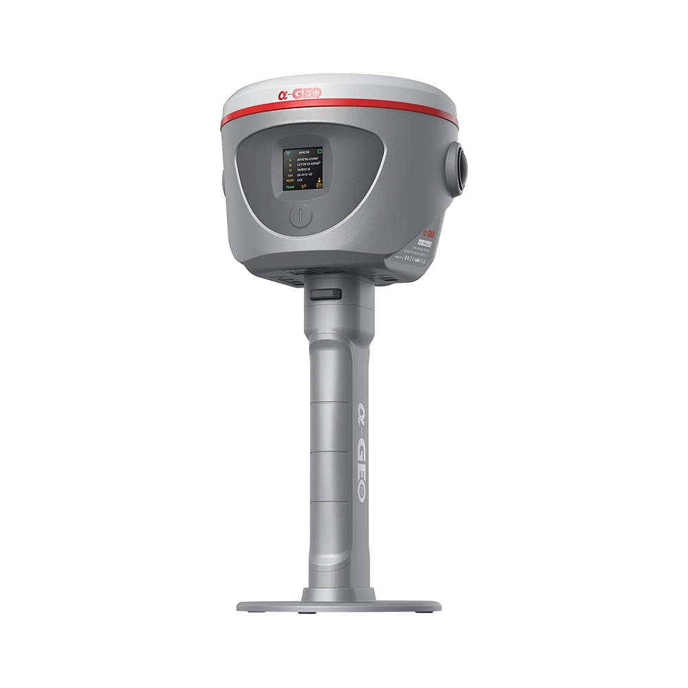
ALPHA GEO proudly presents the Falcon X-a groundbreaking surveying mobile terminal that integrates GNSS, high-precision vision modules, and LiDAR systems to redefine traditional RTK workflows. By combining SLAM technology with high-accuracy RTK and a powerful core processor, it delivers real-time point cloud coordinate calculations and establishes a unified coordinate system across both indoor and outdoor environments. With no need for post-processing, the data is immediately ready for engineering design, greatly improving efficiency and precision.
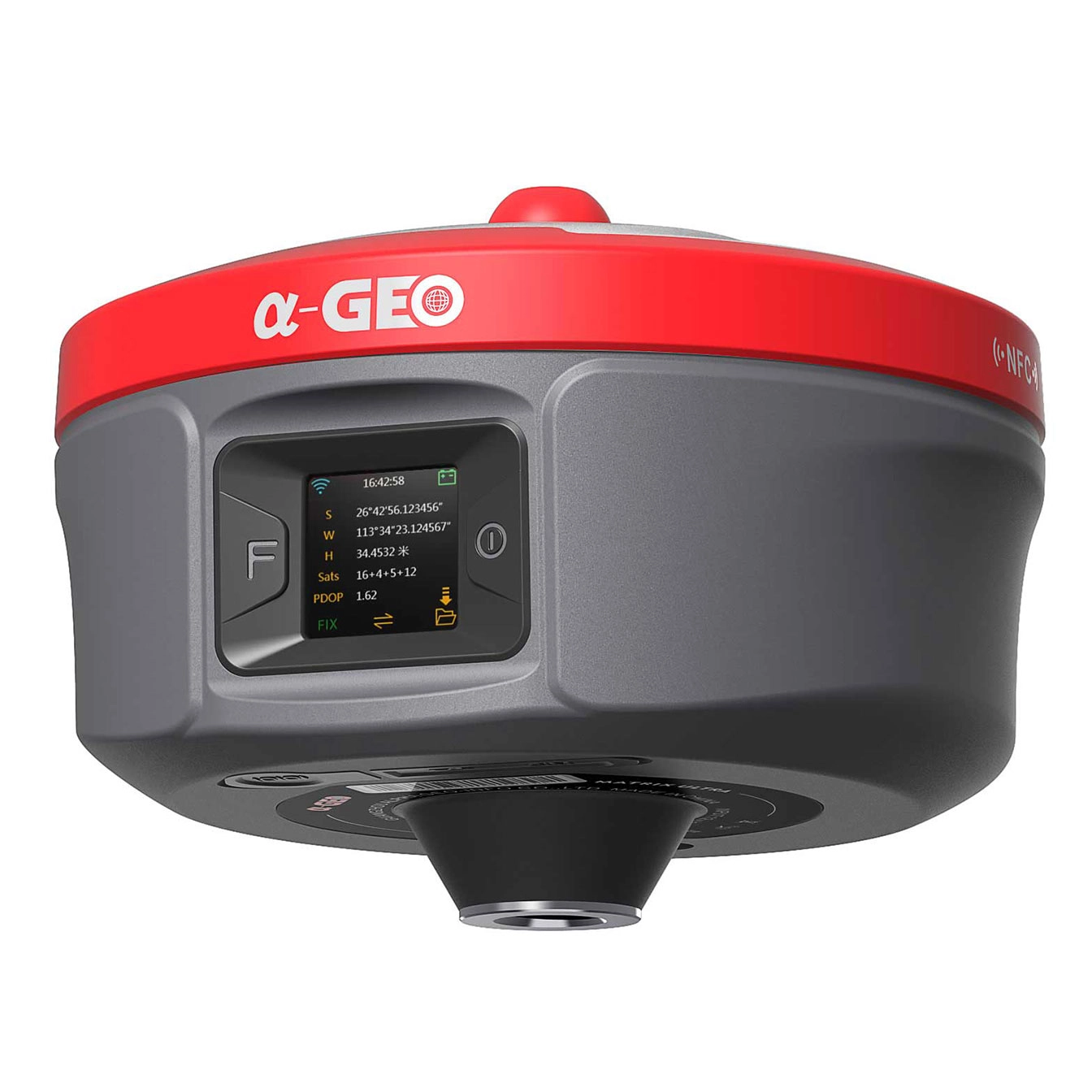
α-GEO, founded in 2008, is a global market-leading high-tech company focusing on high-precision GNSS technology.
alphageognss
alphageo
alphageoinfo